Tab And Slot Sheet Metal Design
Sheet metal design guidelines are followed to design quality sheet metal enclosures. This helps in delivering the product at low cost and faster timelines. All
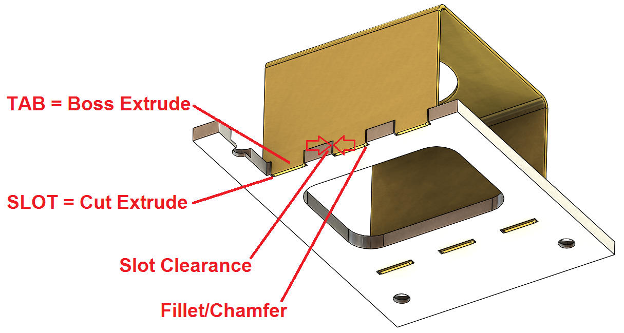
Sheet metal noob - tab and slots. Posted by 1 month ago. Sheet metal noob - tab and slots. Design of go kart chassis using solidworks. Other kits and tables, if you can call them that; listed online are just a piece of sheet metal with holes in it and comes curled up like a taco shell right out of the box. CNC Sheet Laser Parts go together fast and square. Tab and Slot Methodology is used throughout to make it brain dead simple to build a quality tool that lasts forever. For a slot or hole 1' diameter then the minimum distance 'D' = 2.5T + R (see fig. 'C') Form height to thickness ratio – To determine the minimum form height for sheet metal use the following formula: D = 2.5T + R (see below) The height can be less but it required secondary operations and is far more costly. Tab and Slot is commonly used in the metal fabrication industry, especially for low to medium volume production runs. The Tab and Slot feature is available in all parts, not just sheet metal parts. You can use it in single bodies, multi-bodies, and parts in the context of an assembly.
Sheet Metal Design Guidelines
Following points should be considered during the design of sheet metal parts for press bending.
Sheet Metal Material Selection
- Simulation Studies
- Past Experience
- Reverse Engineer existing products
- Experimental Studies
Read this guide to know more about sheet metal material selection Process.
Minimum inside bend Radius for Sheet Metal Parts
Sharp inside bend radius in sheetmetal parts can cause material flow problems in soft material and fracturing in hard material. Which results in localized necking or fracture. Therefore sharp bend radius is not recommended in sheet metal parts.
Bend radius throughout the sheet metal part is kept constant to take the advantage of using the same tool during manufacturing.
Minimum Sheet Metal Bend Length Recommendations
Minimum Hole Diameter Guidelines
Hole/Slot Distance from Bend Edge
Minimum distance between hole/slot edge to bend edge is recommended to avoid metal distortion, deformation and fracturing.

Center to Center Distance Between two Holes
Minimum center to center distance between two holes in sheet metal parts is required to avoid metal distortion, deformation and fracturing.
Recommended Minimum distance between two hole centers in sheet metal design should be equal to sum of hole radius plus two times the sheet thickness.
Recommended Distance = Radius of Hole1 + Radius of Hole2 + Sheet ThicknessEffect of Grain Direction in Sheet Metal Bending
During sheet metal processing ( rolling operation), material grains are arranged in the direction of rolling. When Sheetmetal is bend perpendicular to rolling direction grain rearranges. That has negligible impact on part strength. Whereas bending parallel to rolling direction can lead to cracks because of destruction in grain structure.
Bend Relief in Sheet Metal Bend
Bend relief is provided at the end of the bending edge in sheet metal design to avoid any crack tearing in the corner. Relief height is generally kept greater than two times of sheet thickness plus bend radius.
Extrude Hole Size and Position Guidelines
Creating an extruded hole using a punching process requires extreme pressure/Force. Extruded holes very close to the part edge can lead to sheet metal deformation or tearing. Therefore the minimum distance between the extruded hole to edge if maintained.
Extruded hole to part edge (B) = 3T + D/2Center of extruded Holes (A) = (5 + Hole Dia + 2T)Extruded Hole and bend edge (C) = 3T + R + D/2Round Emboss Design Guidelines
Creating Emboss feature using sheet metal punching requires extreme pressure. Very close emboss to the part edge, can lead to deformation in the sheet metal part.
Tab And Slot Sheet Metal Designs
A – Distance From Emboss To part Edge = 3T + D/2B- Distance Between Two Emboss = (5 + D)C- Distance between Emboss and Sheet Metal bend = 3T + R + D/2Dimple Feature Design in Sheet Metal Parts
Louver Feature Design in Sheet Metal
Minimum distance between louver feature and bending edge is maintained to avoid metal deformation.
(P1) Distance Between Two lowers on Shorter Edge = 5 mm(P2) Distance Between Two lowers on Longer Edge = 8 mm